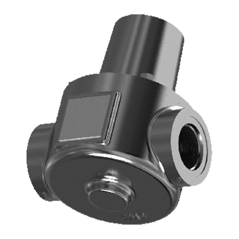
Model 2012
Thermostatic Control Valve
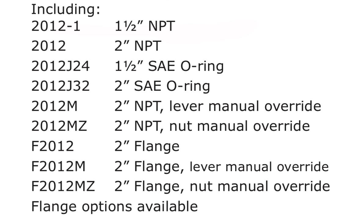
- Connection Sizes: 1 1/2"-2" NPT/BSPP/BSPT, SAE-24, -32, SOCKET WELD, FLANGED
- Diameter: DN40 to DN50
- Three-way thermostatic control valve
- Wide range of temperatures
- Replaceable, non-adjustable, tamper-proof thermostats
- Self-contained unit
- Compact, heavy duty, rugged construction
- Operate in any orientation
Compact and Reliable Temperature Control
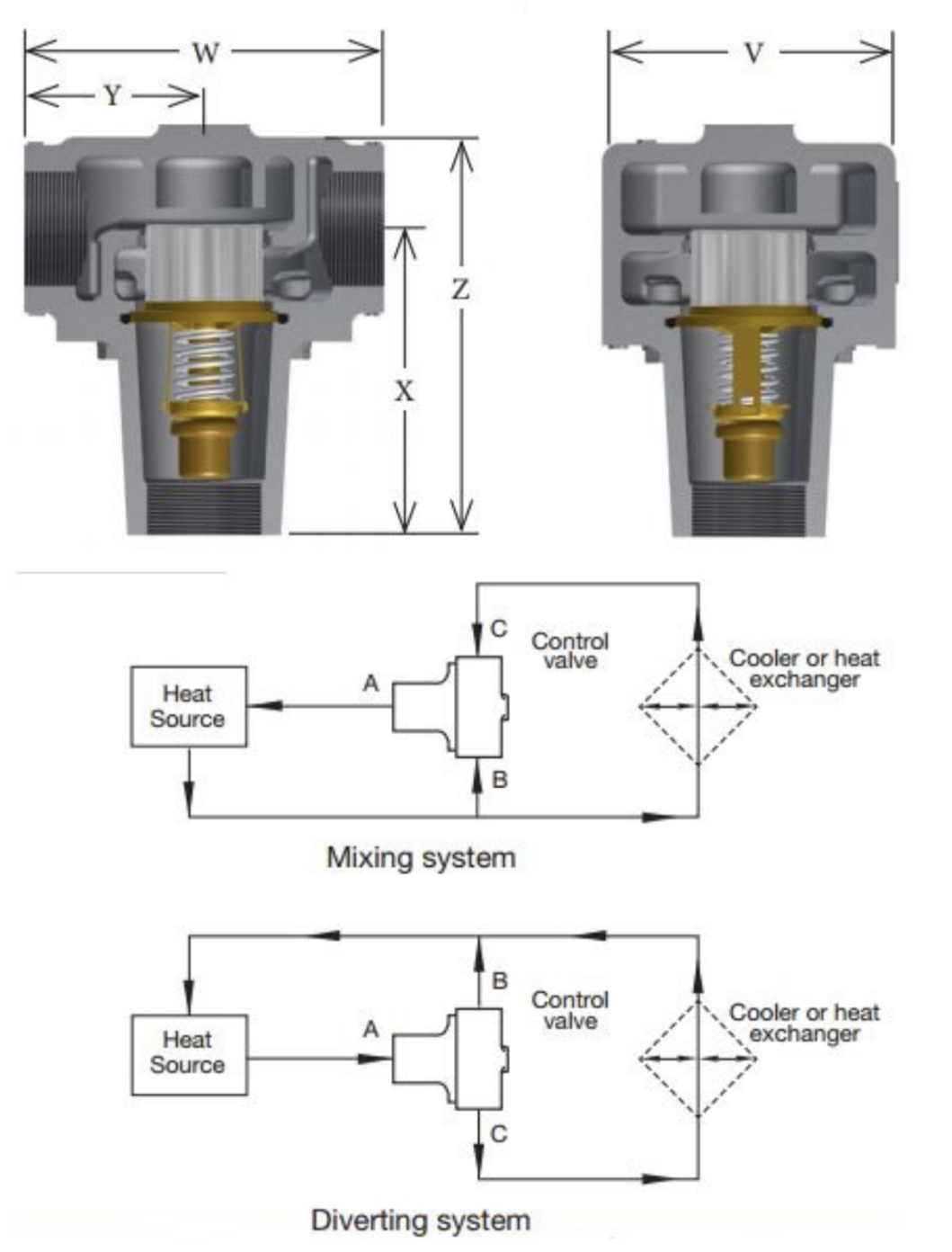
Fluid Power Energy (FPE) thermostatic valves utilize the principle of expanding wax. As the fluid temperature increases, the wax transforms from a solid to a liquid state. This expansion causes the thermostat sleeve to stroke thereby controlling the direction of fluid flow to achieve the required operation.
All FPE valves can be used for diverting or mixing applications without modification of the valve assembly. FPE thermostatic valves are factory set to predetermined set-point temperatures, so no field adjustments are necessary. Simply connect the valve to your system and walk away.
Contact an FPE representative today to see how our thermostatic control valves can enhance your application. Contact Us
Helpful Links
Description
When used in a diverting application, on start-up the total fluid flow is routed back to the main system. As fluid temperature rises to the control range, some fluid is diverted to the cooling system. As fluid temperature continues to increase, more flow is diverted. When the thermostat is in a fully stroked condition, all fluid flow is directed to the cooling system.
FPE thermostatic valves may also be used in a mixing application. Hot fluid enters the “B” port and colder fluid enters the “C” port. The flows mix and the thermostat adjusts flow through ports “B” and “C” to reach the desired temperature, exiting the “A” port.
Standard FPE thermostatic valve housings are made from aluminum and grey iron castings, however, ductile iron, bronze, steel and stainless steel housings are available.
Additional BSP, SAE and JIS threads available.
Dimensions
| Model Number | Body Material* | Connection Size | Principal Dimensions Untis | Flange Drilling | No. of Element | ||||||
| X | Y | W | Z | V | No. of Holes | Dia. of Holes | Bolt Circle | ||||
| *2012 - 1 *2012 - 1M *2012 - 1MZ | "A, B, D, S, SS" | 1 1/2" NPT | 5 15/16 (150) | 3 1/2 (88) | 7 (177) | 8 3/8 (212) | 5 3/4 (146) | N/A | N/A | N/A | 1 |
| *2012 *2012M *2012MZ | "A, B, D, S, SS" | 2" NPT | 5 15/16 (150) | 3 1/2 (88) | 7 (177) | 8 3/8 (212) | 5 3/4 (146) | N/A | N/A | N/A | 1 |
| *2012J24 *2012J24M *2012J24MZ | "A, B, D, S, SS" | SAE 24 1 7/8" - 12 | 5 15/16 (150) | 3 1/2 (88) | 7 (177) | 8 3/8 (212) | 5 3/4 (146) | N/A | N/A | N/A | 1 |
| *2012J32 *2012J32M *2012J32MZ | "A, B, D, S, SS" | SAE 32 2 1/2" - 12 | 5 15/16 (150) | 3 1/2 (88) | 7 (177) | 8 3/8 (212) | 5 3/4 (146) | N/A | N/A | N/A | 1 |
| *F2012 *F2012M *F2012MZ | A | 2" 125lbs FF FLANGE | 6 1/6 (153) | 4 1/2 (113) | 8 15/16 (227) | 9 1/8 (231) | 6 1/2 (165) | 4 | 3/4 (19) | 4 15/16 (125) | 1 |
| B | 2" 150lbs FF FLANGE | 5 7/8 (149) | 4 1/2 (109) | 8 5/8 (219) | 9 1/8 (231) | 6 1/2 (165) | 4 | 3/4 (19) | 4 15/16 (125) | 1 | |
| D | 2" 150lbs FF FLANGE | 6 (152) | 4 1/2 (112) | 8 14/16 (225) | 9 1/4 (234) | 6 1/2 (165) | 4 | 3/4 (19) | 4 15/16 (125) | 1 | |
| S, SS | 2" 150lbs FF FLANGE | 5 15/16 (151) | 4 3/8 (111) | 8 13/16 (223) | 9 3/16 (233) | 6 1/2 (165) | 4 | 3/4 (19) | 4 15/16 (125) | 1 | |
| *F2012X *F2012XM *F2012XMZ | S, SS | 2" 300lbs RF FLANGE | 5 15/16 (151) | 4 9/16 (115) | 9 1/8 (231) | 9 3/16 (233) | 6 1/2 (165) | 8 | 3/4 (19) | 5 (127) | 1 |
| *F2012 - X5 *F2012 - X15M *F2012 - X5MZ | S, SS | 2" 600lbs RF FLANGE | 6 1/4 (158) | 5 (125) | 9 7/8 (250) | 9 4/8 (241) | 6 1/2 (165) | 8 | 3/4 (19) | 4 15/16 (125) | 1 |
| *2013 -1 | "A, B, D, S, SS" | 1 1/2" NPT | 6 (152) | 3 1/2 (88) | 7 (177) | 8 3/4 (222) | 6 1/2 (165) | N/A | N/A | N/A | 1 |
| *2013 | "A, B, D, S, SS" | 2" NPT | 6 (152) | 3 1/2 (88) | 7 (177) | 8 3/4 (222) | 6 1/2 (165) | N/A | N/A | N/A | 1 |
| *2013J24 | "A, B, D, S, SS" | SAE 24 1 7/8" -12 | 6 (152) | 3 1/2 (88) | 7 (177) | 8 3/4 (222) | 6 1/2 (165) | N/A | N/A | N/A | 1 |
| *2013J32 | "A, B, D, S, SS" | SAE 32 2 1/2" - 12 | 6 (152) | 3 1/2 (88) | 7 (177) | 8 3/4 (222) | 6 1/2 (165) | N/A | N/A | N/A | 1 |
| Replace * with body material type: A = Cast iron, AL = Aluminum B = Bronze, D = Ductile iron, S = Steel, SS = Stainless Steel | |||||||||||
Specifications
Model 2012/2013 Specifications
| PRESSURE RATINGS @ 250°F | WEIGHTS | ||||||||
| Material | A | B | D | S | SS | A | B | D | S & SS |
| psi | 150 | 180 | 225 | 670 | 590 | 32 (15) | 39 (18) | 32 (15) | 36 (16) |
| Bar | 10.3 | 12.4 | 15.5 | 46.2 | 40.6 | ||||
| SERVICE KITS (xxx represents temperature °F) | |||||||||
| MODEL | O-RING | GASKET | LIPSEAL | THERMOSTAT | |||||
| 2000-xxx | 1 of Buna-N | 1 | 1 | 1 | |||||
| 2000V-xxx | 1 of Viton | 1 | 1 | 1 | |||||
| 2000E-xxx | 1 of Neoprene | 1 | 1 | 1 | |||||
| LIP SEAL INSERTION TOOLS | LIP SEAL EXTRACTION TOOLS | ||||||||
| Part Number | Component | Part Number | Component | ||||||
| 2071-IT | Lip Seal Insertion Plug | 2071-RT | Lip Seal Extraction Plug | ||||||
| NOTE: Service Kits are supplied with Housing O-Rings & Housing Gaskets. Make sure to replace your original housing seal using the same style seal, and discard the extra component. If your valve was originally supplied with a gasket, DO NOT attempt to use an O-Ring, as the seal will leak without a groove to accept the O-Ring | |||||||||
| Note: FPE reserves the right to substitute ordered material for better quality. | |||||||||